A filling machine may look simple, but its working environment can be complex. It may handle alcohol-based liquids, solvents, fragrances, or other flammable materials. During filling, vapors can collect around nozzles, pumps, valves, and containers. A small electrical spark may then become a serious ignition source.
Why is explosion-proof design needed for certain filling machines? The answer begins with controlling ignition risks in classified or potentially hazardous areas. Explosion-proof equipment helps contain internal sparks and limits the chance of ignition spreading outward. Proper systems may include sealed motors, protected control panels, grounded components, suitable sensors, and carefully selected pneumatic or electrical parts. Each detail matters.
Real factory experience shows that design is only one part of safe operation. Installation quality, ventilation, cleaning, maintenance, and operator training also influence risk. Engineers should assess the liquid’s flash point, vapor behavior, filling speed, temperature, and surrounding atmosphere. They should also verify equipment certifications and regional requirements before production begins. Guesswork is not enough.
A reliable manufacturer documents these decisions clearly. It explains why each component was selected and how the machine should be inspected. Still, no design removes every risk. That limitation deserves honest attention. Sometimes users focus on the machine body and overlook hoses, grounding straps, or damaged seals. Small failures can matter. Regular checks, accurate records, and realistic risk assessments help maintain protection over time. This article examines the engineering principles, practical safeguards, and selection criteria behind explosion-proof filling machines.
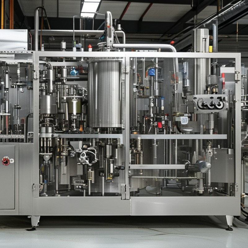
A filling machine becomes hazardous when it operates near flammable vapors, combustible dust, or easily ignited liquids. During filling, splashing and turbulence can release vapor around the nozzle. Small leaks may collect beneath conveyors, inside cabinets, or near drainage points. A motor, relay, overheated bearing, or static spark can then provide enough energy for ignition. Even a warm metal surface can matter in a poorly ventilated area.
Explosion-proof design reduces these ignition possibilities through several coordinated measures. Sealed electrical enclosures help prevent internal sparks from reaching the surrounding atmosphere. Grounding and bonding control static electricity during liquid transfer. Temperature monitoring limits heat from motors, pumps, and bearings. Components must also suit the site’s hazardous-area classification, product properties, and operating conditions. One design cannot fit every facility.
The surrounding process deserves equal attention. Operators need clear procedures for grounding checks, leak inspection, ventilation, and safe cleaning. A damaged seal can change the risk quickly. In real installations, small oversights often matter more than impressive specifications. For example, a forgotten grounding strap or blocked vent may undermine otherwise careful engineering. No machine removes every risk. Design reviews should include filling speed, container shape, cleaning chemicals, maintenance access, and possible vapor release points. That practical review is where safety becomes reliable.
Flammable vapors can form explosive mixtures with air during filling, dosing, and cleaning operations. The chart shows the approximate flammable range of common substances in air, defined by their lower and upper explosive limits.
A mixture can ignite when its vapor concentration falls between the lower explosive limit (LEL) and upper explosive limit (UEL). Explosion-proof filling machines help prevent ignition by controlling electrical sparks, hot surfaces, static discharge, and other potential ignition sources. Values are approximate volume percentages in air and may vary with temperature and test conditions.
During filling, danger often begins before the product enters the container. Flammable liquids release vapor when splashed, warmed, or transferred at high speed. A small leak around a valve can create a vapor cloud near motors, switches, or static-charged surfaces. The UK Health and Safety Executive states that one litre of liquid can produce hundreds of litres of vapor, depending on its temperature and composition. Vapor needs only an ignition source and the right concentration. That is the uncomfortable part.
Filling heads can also build static electricity, especially with low-conductivity liquids and plastic containers. Poor bonding, open transfers, and inadequate ventilation increase exposure. In its Imperial Sugar investigation, the U.S. Chemical Safety Board reported 14 deaths and 36 injuries after combustible dust ignited in 2008. The material differed, but the lesson applies: hidden fuel and a routine ignition source can combine quickly. Explosion-proof design uses certified electrical equipment, grounded conductive paths, sealed controls, and suitable ventilation. It also considers cleaning, because residue can become fuel. The term “explosion-proof” is not a complete risk assessment.
Tips: Verify the liquid’s flash point and vapor density before selecting equipment. Bond and ground the machine, container, and transfer line. Keep ignition sources outside classified areas. Measure ventilation performance, not merely fan operation. Inspect seals, hoses, and nozzles for small leaks. Train operators to stop filling after abnormal odors or static discharge. A practical review should challenge its own assumptions. Temperature changes, new formulas, and human shortcuts can weaken yesterday’s safeguards.
Sources: UK HSE, Safe Use and Handling of Flammable Liquids; U.S. Chemical Safety Board, Investigation Report: Sugar Dust Explosion and Fire.
Why Do Some Filling Machines Need Explosion Proof Design?
Filling machines handling flammable liquids may create combustible vapors near motors, sensors, and control panels. A small electrical spark can become a serious ignition source. Explosion-proof design reduces this risk through controlled equipment selection and careful engineering.
Which Safety Features Define an Explosion-Proof Filling Machine?
A reliable machine uses sealed electrical enclosures, approved cable glands, and properly rated motors. These parts help prevent sparks or hot surfaces from contacting vapors. Grounding and bonding also control static electricity during filling. Pneumatic equipment can reduce electrical exposure in critical areas. Pressure controls, emergency stops, and guarded moving parts add another layer of protection. The machine should match the site’s hazardous-area classification, product properties, and filling temperature.
In practical installations, technicians also check ventilation, leak paths, and cleaning procedures. A robust design includes documented risk assessments, inspection records, and clear maintenance instructions. Certification matters, but it does not replace correct installation. No system is perfect. That is worth admitting. Poor grounding or a damaged seal can weaken an otherwise sound machine.
Tips: Confirm the liquid’s flash point and vapor behavior before selecting equipment. Inspect seals, cables, and grounding points regularly. Train operators to stop the machine when unusual heat, odor, or vibration appears. Keep records; memory is not a safety system.
Some filling machines handle flammable liquids, vapors, or combustible powders. A tiny spark can become a serious event inside a production area. Explosion-proof design reduces ignition risks around pumps, sensors, motors, and control cabinets. It uses sealed electrical parts, controlled surface temperatures, reliable grounding, and suitable enclosure protection.
OSHA’s combustible-dust data for 1980–2005 recorded 281 incidents, 119 deaths, and 718 injuries. The figures remain a warning for powder filling operations. NFPA 652 also emphasizes hazard analysis, dust control, and documented prevention measures. In practice, a properly designed machine keeps hot surfaces away from vapors. It also limits sparks near exposed product. Workers should see this protection in details: bonded metal piping, closed transfer lines, and clean floors without powder layers. Yet “explosion-proof” is not a magic label. Incorrect zoning, poor maintenance, or an unsuitable seal can weaken the whole system.
Tips: Confirm the hazardous-area classification before selecting equipment. Check grounding continuity during scheduled inspections. Clean powder deposits before they spread. Review the filling process after every material change. A practical improvement is often missed: train operators to report unusual heat, odor, or static shocks immediately. Production pressure can make small warnings seem harmless. They are not.
| Design Dimension | Typical Hazard or Requirement | Relevant Classification or Reference | Explosion-Proof Design Response | Protection Benefit |
|---|---|---|---|---|
| Flammable liquid vapors | Solvents, fuels, alcohol-based products, and other liquids can release vapors that form an ignitable mixture with air. | Hazardous-area classification is determined by the frequency and duration of the flammable atmosphere. | Use suitably certified electrical equipment, sealed or purged enclosures, controlled ventilation, and equipment bonding and grounding. | Reduces the chance that electrical arcs, hot surfaces, or static discharge will ignite vapor. |
| Combustible dust | Powders such as food ingredients, pharmaceuticals, resins, and metals may create combustible dust clouds or dust layers. | IEC/ATEX dust zones include Zone 20, Zone 21, and Zone 22, based on the likelihood and duration of dust presence. | Apply dust-tight enclosures, suitable ingress protection, temperature control, dust extraction, and cleaning procedures that prevent accumulation. | Limits dust entry into equipment and prevents hot surfaces or electrical faults from igniting dust clouds. |
| Gas and vapor zones | Vapor may be continuously present, likely during normal operation, or present only briefly under abnormal conditions. | IEC/ATEX Zone 0: continuous or long periods; Zone 1: likely occasionally in normal operation; Zone 2: not likely in normal operation and, if it occurs, exists briefly. | Select equipment with a protection concept and certification appropriate to the assigned zone and gas group. | Matches the machine’s ignition protection level to the actual probability of an explosive atmosphere. |
| Surface temperature | A machine component can ignite a vapor or dust atmosphere if its surface temperature exceeds the material’s ignition temperature. | For gas equipment, IEC temperature classes include T1 ≤450°C, T2 ≤300°C, T3 ≤200°C, T4 ≤135°C, T5 ≤100°C, and T6 ≤85°C. | Use temperature-rated motors, sensors, heaters, bearings, and control components; monitor abnormal temperature rise where required. | Prevents normal operation or foreseeable faults from creating an ignition-capable hot surface. |
| Static electricity | Liquid flow, powder transfer, flexible hoses, belts, and synthetic components can generate electrostatic charge. | Static-control measures are part of recognized hazardous-area risk-reduction practices and should be verified for the process. | Bond and ground conductive components, use appropriate antistatic materials, control transfer velocity where necessary, and verify electrical continuity. | Reduces spark risk during filling, conveying, container handling, and cleaning. |
| Electrical and control equipment | Motors, switches, relays, terminals, variable-frequency drives, and sensors may produce sparks or hot spots. | Equipment should be certified or approved for the applicable hazardous location, gas or dust group, temperature class, and protection level. | Use certified components, intrinsically safe circuits where suitable, flameproof or increased-safety enclosures, and properly installed cable entries. | Contains or prevents ignition sources and reduces the likelihood of fault energy reaching the hazardous atmosphere. |
| Filling and dosing point | The product inlet, nozzle, container opening, and transfer area can be the location where vapor or dust is released most directly. | Local area classification should be based on release rate, ventilation, product properties, operating temperature, and process conditions. | Use closed transfer where practical, local exhaust ventilation, suitable nozzles, splash and vapor control, and compatible certified components. | Reduces the concentration and spread of flammable material around operators and nearby equipment. |
| Mechanical ignition sources | Misalignment, friction, impact, worn bearings, or foreign objects can generate heat or sparks. | Ignition-source control should be included in the machine’s documented risk assessment and preventive-maintenance program. | Use non-sparking or suitably selected materials where required, control clearances, monitor bearings, and maintain lubrication and alignment. | Reduces ignition risk from moving parts that are not electrical in origin. |
| Pressure and flame containment | An internal ignition may create pressure and flames that could propagate through joints, shafts, cable entries, or connected pipework. | Protection concepts may include flameproof containment, explosion venting, suppression, isolation, or other methods selected by the equipment design. | Use certified joints and glands, controlled enclosure construction, isolation devices, and pressure-relief systems where the risk assessment requires them. | Limits flame propagation and reduces the consequences of an internal ignition. |
| Ventilation and gas detection | Insufficient ventilation can allow vapors to accumulate, especially near low points, enclosed machine sections, or dispensing areas. | Ventilation effectiveness and detector placement should be determined from the material properties and the facility risk assessment. | Provide engineered ventilation, suitable gas or vapor detection, alarms, and automatic shutdown or isolation functions when required. | Helps prevent the atmosphere from reaching an ignitable concentration and enables rapid response to leaks. |
| Cleaning and maintenance | Product residues, dust layers, leaks, and damaged seals can change the original hazardous-area conditions. | Equipment certification does not replace housekeeping, inspection, maintenance, and operational controls. | Schedule inspections, remove dust safely, test bonding and grounding, replace certified parts correctly, and control hot work. | Preserves the intended protection level throughout the machine’s service life. |
| Worker protection | Operators may be exposed to flash fire, smoke, pressure effects, flying fragments, or harmful process chemicals after an incident. | Final safeguards depend on the site risk assessment, applicable occupational-safety rules, and emergency procedures. | Combine explosion-protected equipment with guarding, interlocks, emergency stops, training, personal protective equipment, and evacuation controls. | Reduces both the probability of an incident and the potential severity of injuries. |
| Production continuity | An ignition event can damage machinery, contaminate products, stop production, and create long recovery times. | Risk reduction should consider both personnel safety and credible loss scenarios for the process. | Use preventive monitoring, certified components, leak prevention, automatic shutdown, planned maintenance, and documented change control. | Reduces unplanned downtime, equipment damage, product loss, and interruption to production areas. |
| Important: The correct explosion-protection concept cannot be selected from the product name alone. It should be based on the processed material’s flash point or dust characteristics, release sources, ventilation, operating temperature and pressure, hazardous-area classification, and applicable local regulations and certification requirements. | ||||
Explosion-proof filling machines are most common where liquids release flammable vapors during filling. These environments include chemical plants, paint workshops, adhesive production lines, and solvent-based coating facilities. They also appear in selected cosmetic and pharmaceutical areas using alcohol-rich formulas. The risk often begins at the filling nozzle. A small spark, hot surface, or static charge can ignite vapor near an open container.
In practice, operators use these machines for bottles, cans, pails, and drums. Typical products include cleaning solvents, industrial coatings, sealants, and specialty liquids. The machine may use sealed electrical enclosures, grounded metal parts, and pneumatic controls. Ventilation is equally important. Explosion-proof equipment cannot correct poor room design or careless material handling. That point is sometimes overlooked.
Qualified engineers normally assess the hazardous area before selecting equipment. They check vapor characteristics, filling temperature, container size, and production speed. Certified components must match the site’s classification and operating conditions. A machine suitable for one facility may not suit another. This is where purchasing decisions can become imperfect. Buyers sometimes focus on filling accuracy while ignoring grounding, bonding, or maintenance access. During operation, workers should inspect cables, seals, nozzles, and earth connections regularly. Small defects matter. Industry experience shows that safety depends on the complete filling system, not the machine label alone.
: Flammable liquids can release vapor during splashing, warming, or fast transfer. Vapor needs the right concentration and an ignition source. A small valve leak may form a cloud near a motor or switch.
Useful features include sealed electrical enclosures, rated motors, approved cable glands, and controlled surface temperatures. Grounded paths help control static electricity. Pneumatic components may reduce electrical exposure in critical areas.
Filling heads, containers, and transfer lines can accumulate static charges. Bonding connects conductive parts. Grounding gives electricity a safer path away from vapor. Poor contact can quietly defeat the protection.
Measure actual airflow and vapor removal. Do not rely only on a running fan. Inspect dead zones near filling heads, valves, and low points. The air may look clear.
Check seals, hoses, nozzles, valves, and cable entries. Look for damp spots, unusual odors, or residue. Small leaks deserve attention before production continues. Stop and investigate.
No. The machine must match the area classification, liquid properties, temperature, and installation. Damaged seals, poor grounding, or incorrect zoning can create serious weaknesses. A label is not a complete risk assessment.
Review the process after changing formulas, temperatures, containers, or transfer speeds. Cleaning methods also matter because residue can become fuel. Yesterday’s safeguards may not fit today’s process.
Stop filling after static shocks, abnormal heat, strong odors, vibration, or visible leakage. Keep ignition sources away from the affected area. Report the condition and document the response. Production pressure can distort judgment.
Some filling machines operate in environments where liquids, powders, or vapors can ignite easily. During filling, flammable materials may release combustible fumes, while pumps, motors, electrical controls, static electricity, or friction can create ignition sources. Why is explosion-proof design needed for certain filling machines? It is needed to reduce the possibility that normal equipment operation will trigger a fire or explosion in areas containing hazardous atmospheres.
An explosion-proof filling machine typically uses protected electrical components, sealed enclosures, grounding and bonding systems, controlled operating temperatures, and designs that limit sparks and static buildup. These features help contain or prevent ignition, protecting workers, equipment, and surrounding production areas. Such machines are commonly used in industries that handle flammable liquids, solvents, coatings, chemical ingredients, fuels, aerosols, or other materials capable of producing combustible vapors or dust. Proper ventilation, inspection, maintenance, and operating procedures should work together with the machine’s safety design to support reliable and responsible production.

Yongli Machine